Gadget
2010/05 – 2010/08
1 Introduction
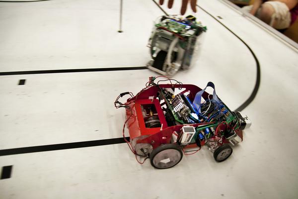
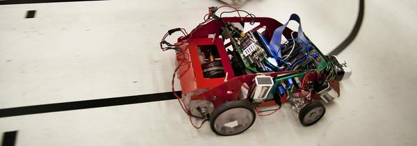
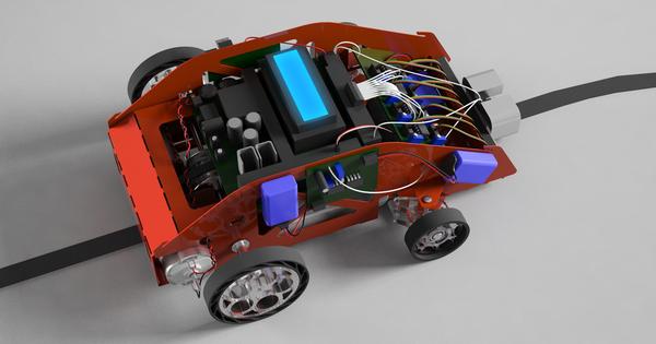
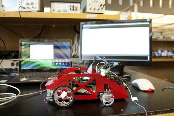
Gadget is a fully autonomous robot that follows a black tape on a white surface at high speed. It uses eight QRD 1114 sensors to track the position of the tape. An onboard TINAH board using an ATMega 128 processor controls the robot using a simple state machine.
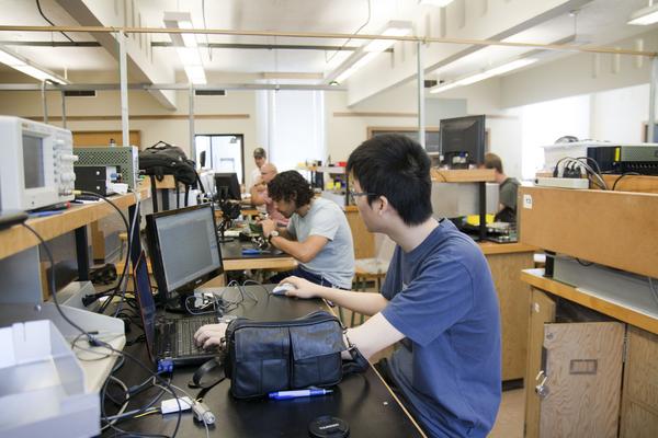
Gadget was created as a team of four in the second year of my undergraduate curriculum for the course “Phys 253 — Introduction to Instrument Design”. My team included Russell Vanderhout, Adrien Emery, and Billy Fung.
2 Design
Gadget features many interesting design choices not found in the robots of other teams.
2.1 Mechanical design
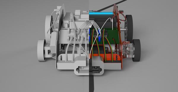
I did most of the mechanical design for the robot. It took several iterations before we got it working satisfactorily.
2.1.1 Chassis
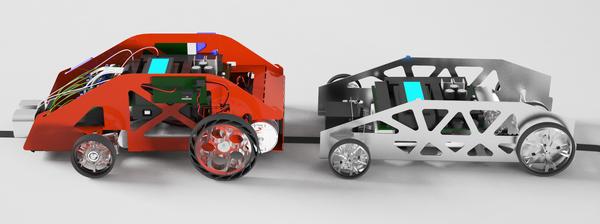
The chassis is manufactured from a single sheet of 22-gauge steel cut using an OMAX waterjet cutter.
- Version 1: The first version was designed in SolidWorks and had the front wheels extended out on arms. However, this was not viable since those arms were too weak.
- Version 2: This addressed the issues of Version 1, but the long wheelbase made steering difficult and there was not enough space to hold the circuitry.
- Version 3: A completely new chassis developed from scratch, with a much shorter wheelbase. This chassis had many tabs for mounting all kinds of things, such as the transverse mid-mounted motors. However, there was again not enough space.
- Version 3.4: The position of the motors and the rear axles was interchanged. The short 13.4 cm wheelbase greatly improved corner manoeuvrability.
- Version 3.5: More aesthetic rounded corners with more space in front for the amplifier circuits for the QRD1114 sensors.
- Version 4: The final design features an enclosure for the rear drivetrain. A change in the rules allowed an elongated front for a more forward placement of the QRD1114 sensors. Minor improvements include better clearance for the steering mechanism and the ability to slide the motors backwards to adjust tension in the drive belt.
Only chassis versions 2, 3.5, and 4 were actually manufactured. The latter two were powder-coated red.

2.1.2 Drivetrain
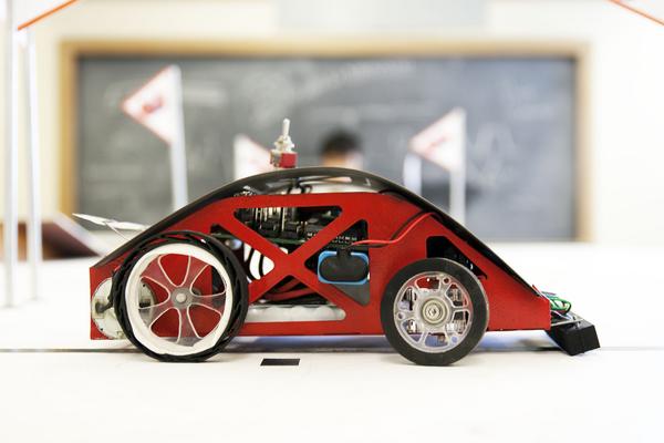
Gadget has two transversely mounted electric motors mated to a 13-tooth sprocket. The sprocke transmits power to a 24-tooth differential gear via a timing belt. The differential gear allows full power to be transmitted even during turns.
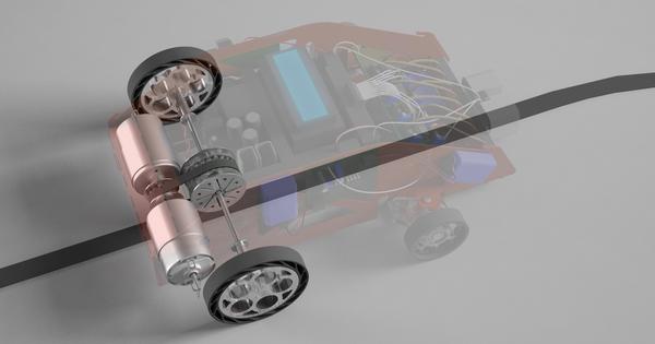
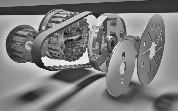
The differential gear was manufactured from several pieces of laser-cut acrylic. A video of the cutting process can be found on Youtube.
2.1.3 Steering
The steering is controlled by a servo motor. Front wheels are mounted on laser-cut acrylic parts. The usage of ball bearings allows the front wheels to rotate smoothly and frictionlessly, whilst allowing precise steering.
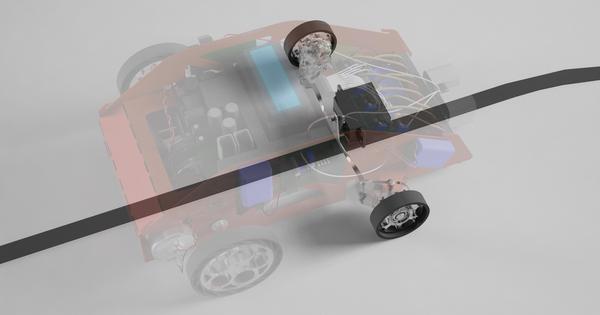
The steering mechanism is carefully designed according to the Ackermann geometry. A priority was to improve the mechanical advantage of the servo motor so that a small movement of the servo would result in a large change in steering angle, so that performance is less bottlenecked by the speed of the servo motor. As it turns out, however, performance is still bottlenecked by the servo motor and we had to buy a new one with a response time almost twice as fast, and with more torque. The new servo decreased our lap time from around 18 seconds to 12 seconds.
One of the things most prone to failure was the linkage connecting the two front wheels. This linkage was originally cut in 24-gauge steel, then in 22-gauge, and then ultimately in 18-gauge.
2.1.4 Shell
Each robot is required to have an infrared emitter mounted at a height of six inches. We designed a shell to mount the said emitter as well as for cosmetic purposes.
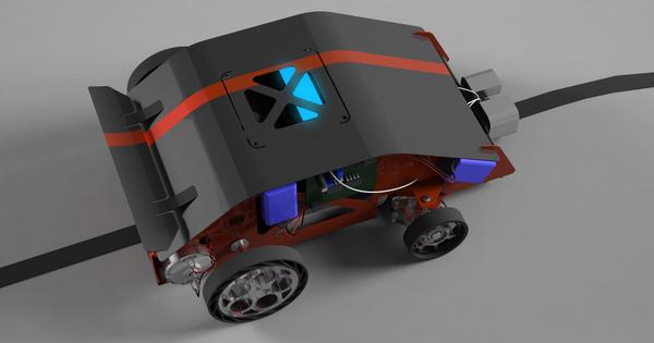
A rear spoiler was spot-welded on for fun. Both the shell and the spoiler are made in 24-gauge steel, and powder-coated black. A red racing stripe was added using red tape.
2.1.5 Wheels
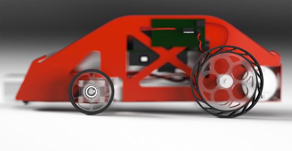
The wheels on Gadget were made from polycarbonate, and the tyres from rubber. Both are cut using the waterjet cutter. The design of the rear wheels evokes the famous five porthole wheels on the Lamborghini Countach. The rear tyres flex in a similar way to the Michelin Tweel to improve ground contact.
2.2 Electrical Design
The electrical design was mostly done by Billy and Adrien. Billy was largely responsible for designing and soldering the comparator circuit for the QRD1114 sensors for tape tracking; Adrien was largely responsible for the circuits involving the rangefinder and motor control. Adrien also designed and constructed the infrared detector and filter, although this was not used.
2.2.1 QRD1114 comparator circuit
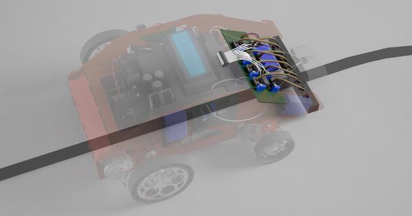
The comparator circuit receives the analog signal of the QRD1114 and outputs either digital HIGH or LOW based on a threshold that is adjusted using a potentiometer. It uses one dual comparator for every two QRD sensors. Although it was originally planned to have eight potentiometers, one to calibrate each QRD sensor, only four were used in the end. This was because, after soldering three potentiometers, it became apparent that QRD1114 sensors were sufficiently alike that only one potentiometer would suffice to calibrate them all. Besides, tuning the potentiometer is a lot more tedious than simply giving the sensor a physical nudge with a popsicle stick, which usually accomplishes the same effect.
2.2.2 Rangefinder circuit
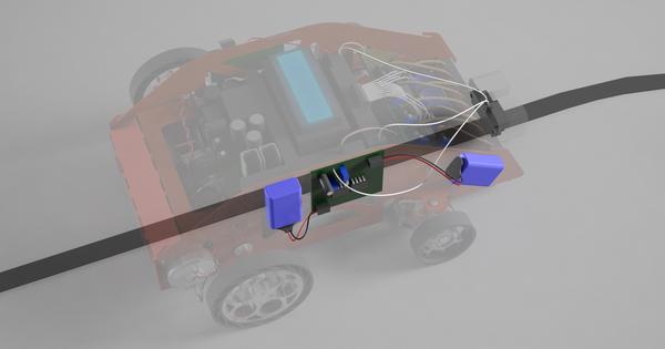
Gadget is equipped with an infrared rangefinder at the front to detect obstacles. Adrien soldered the rangefinder comparator circuit to convert the analog signal of the rangefinder to either HIGH or LOW to indicate the presence of an obstacle.
A low-pass resistor-capacitor filter was constructed to mitigate the issues of noise from extraneous infrared sources. In addition, the rangefinder is encased in a solid metal block that is grounded to reduce noise.
2.2.3 Infrared sensor
Adrien soldered a sallen-key band pass filter, amplifier, dc-block, and peak detector for the infrared sensor circuit. Since an infrared emitter is mounted on each robot, such an infrared sensor would allow Gadget to avoid other robots. However, this idea was scrapped in favour of the rangefinder, which could avoid all obstacles.
3 Software
The code for Gadget is written in the Wiring language for the UBC Engineering Physics custom-designed TINAH board with the Atmel ATMega128 16MHz microprocessor, similar to that of the more famous Arduino systems.
The code was jointly written by Russell Vanderhout and me and can be accessed here in the same condition as was used on competition day.
3.1 Tape-following algorithm
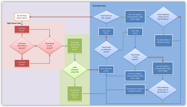
Gadget has more tape-sensing QRD1114 sensors than any other robot of its year, and thus there ought to be an algorithm to give it some advantage over its competitors. To efficiently read and process all eight sensors, Russell devised the “Two-Eight” method which has two states:
- Eight sensor scan: the robot scans each of the eight sensors from left to right. Once a sensor “sees” the tape, it sets that sensor as the reference sensor and enters Two Sensor Scan.
- Two sensor scan: the robot scans the reference sensor, and the one on the right of it. If only the left one sees the tape but not the right one, it shifts the reference sensor leftwards if the reference sensor is currently right of the center; in the opposite case, it shifts the reference sensor rightwards if it is currently left of the center. If both relevant sensors are on the tape, then no shifting occurs; if nothing is detected, it switches to Eight Sensor Scan.
In each iteration of Two Sensor Scan, if at least one sensor is on, it sends an instruction to the steering servo motor. The tape is either exactly under one sensor, with eight different possibilities, or in between two adjacent sensors (both of which read positive), with seven different possibilities. So, there are fifteen possible angles. Hence, the instruction sent to the angle is the appropriate one from a lookup table containing 15 angles.
This is essentially proportional control with a nonlinear actuation curve, possible only through the large number of sensors we have.
| angle | sensor 0 | sensor 1 | sensor 2 | sensor 3 | sensor 4 | sensor 5 | sensor 6 | sensor 7 |
|---|---|---|---|---|---|---|---|---|
| 1 | 0 | 0 | 0 | 0 | 0 | 0 | 0 | |
| 1 | 1 | 0 | 0 | 0 | 0 | 0 | 0 | |
| 0 | 1 | 0 | 0 | 0 | 0 | 0 | 0 | |
| 0 | 1 | 1 | 0 | 0 | 0 | 0 | 0 | |
| 0 | 0 | 1 | 0 | 0 | 0 | 0 | 0 | |
| 0 | 0 | 1 | 1 | 0 | 0 | 0 | 0 | |
| 0 | 0 | 0 | 1 | 0 | 0 | 0 | 0 | |
| 0 | 0 | 0 | 1 | 1 | 0 | 0 | 0 | |
| 0 | 0 | 0 | 0 | 1 | 0 | 0 | 0 | |
| 0 | 0 | 0 | 0 | 1 | 1 | 0 | 0 | |
| 0 | 0 | 0 | 0 | 0 | 1 | 0 | 0 | |
| 0 | 0 | 0 | 0 | 0 | 1 | 1 | 0 | |
| 0 | 0 | 0 | 0 | 0 | 0 | 1 | 0 | |
| 0 | 0 | 0 | 0 | 0 | 0 | 1 | 1 | |
| 0 | 0 | 0 | 0 | 0 | 0 | 0 | 1 |
3.2 Lane-changing
The track of the Roborace has two lanes. Avoiding obstacles entails detecting the obstacle and then switching to the other lane. A boolean variable keeps track of the lane on which Gadget is travelling, and once the rangefinder detects an obstacle for longer than some threshold, the following algorithm executes:
- Set the servo motor to an angle such as to steer towards the other lane.
- Proceed at this steering angle until all eight sensors do not detect the tape anymore.
- Set the servo motor to go straight.
- Proceed until the tape track is detected on the side of the robot away from the new lane. The reason for this slight “overshoot” is because if the tape was on the same side as the new track, the standard tape following algorithm would make it forcefully steer into the new track (even though it is already angled to enter this track) and result in unacceptable oscillations and even failure of the tape-following algorithm. However, overshooting slightly would result in an elegant and smooth lane re-entry.
3.3 Motor control
Gadget is capable of very high speeds because it uses more powerful motors (and it has two of those) than most other robots. However, the servo motor requires time to respond; as such, moving at too great a speed may cause oscillations since the robot is simply unable to steer fast enough. Hence, the robot is usually run at roughly 70% pulse width modulation duty cycle.
To avoid skidding, the robot brakes at the start of turning, by setting the duty cycle to some value determined by a lookup table. After a predetermined braking time, the robot accelerates at full duty cycle for a short time before returning to its usual speed.
3.4 Optimizations
The source code uses many lookup tables and inlines several functions. It can scan the tape over 15,000 times per second.
4 Performance
Our friend Anson Liang took a video of our robot giving some idea of its speed, although in the video it suffered from some oscillation.
It could lap the inner track in 11 seconds and the outer track in 12 seconds. The only robots that are consistently faster are Adiabatmobile (8 seconds) and Elvis (10 seconds).
Gadget is capable of detecting and avoiding obstacles around 30 cm ahead of it. However, despite our efforts to shield the rangefinder, it often activated due to ambient infrared noise. For this reason, it failed to work properly during the actual race. However, right after the race, we unplugged the rangefinder and the robot ran about 100 laps flawlessly at high speed, impressing the audience.
