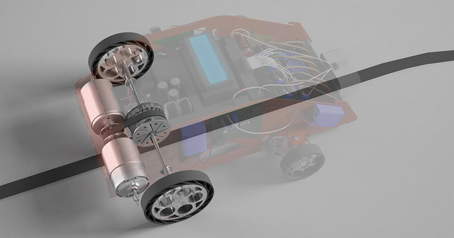
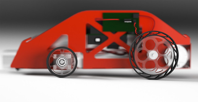
The design of Gadget

The above is a 3D render of Gadget. Model created in Rhinoceros 3D, rendered with VRay for Rhino, postproduction work in Photoshop. Click on it for a high-resolution version that you can put on your wall or something.
Gadget features sophisticated mechanical design and electrical design.
Mechanical Design
The mechanical aspect of Gadget was almost entirely designed and fabricated by Daniel. However, Adrien also provided some insight and helped with assembly.
Chassis

The chassis, designed from scratch by Daniel, has gone through multiple iterations. Seen above is versions 2 and 4. Only three versions of the chassis were actually manufactured: v2, v3.5, and v4, all in 22-gauge steel. The latter two versions were powder-coated red. Chassis v2 has been discarded, v3.5 is now in Daniel's living room as a souvenir, and v4 is still in Gadget.
Below, you may see all the different iterations of the chassis.

Drivetrain
Gadget has two Princess Auto motors driving one 13-tooth sprocket, which transmits power to the 24-tooth differential gear housing via a timing belt. A differential gear, rather than software differential or a differential drive, was chosen because a mechanical differential allows full power to be transmitted even during turns.
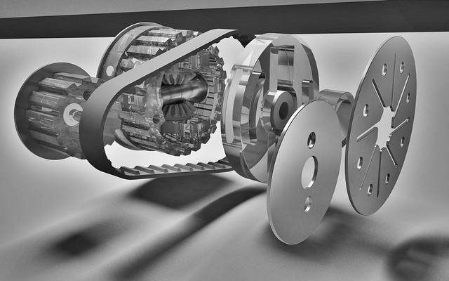
The differential gear, which Daniel designed from scratch, was fabricated from acrylic with the laser cutter. It turns out to be one of the most complicated and well thought-out mechanical components among the 14 competing teams this year. After one major redesign and several minor ones, it now functions very well. Below is a schematic of the differential gear on a one-millimetre grid:

Thanks to Jon Nakane and Bernhard Zender, we were able to fabricate the acrylic parts of the differential gear using a state-of-the-art laser cutter. Below is a video of an earlier version of the differential gear, with accompanying wheels, being cut out. The parts being cut out in the video also includes a steering mechanism for chassis v2.
Although the sprocket between the motors appears to be simple, mounting those motors is a nontrivial task. Initial versions of the sprocket also lacked a flange; the metal flange was added after the belt kept sliding off. Maintaining appropriate tension on the belt has also been a challenge. The latest version of the chassis allows both motors and sprocket to be slid backwards to adjust the tension.
Steering
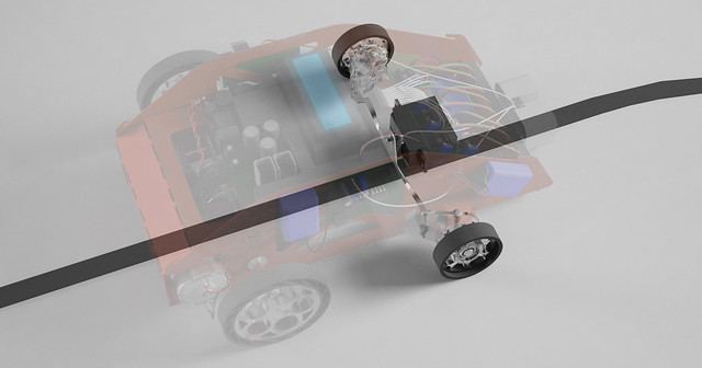
Front wheels are mounted on laser-cut acrylic parts. The usage of ball bearings allows the front wheels to rotate smoothly and frictionlessly, whilst allowing precise steering.
The steering mechanism is carefully designed according to the Ackermann geometry. A priority was to improve the mechanical advantage of the servo motor so that a small movement of the servo would result in a large change in steering angle, so that performance is less bottlenecked by the speed of the servo motor. As it turns out, however, performance is still bottlenecked by the servo motor and we had to buy a new one with a response time almost twice as fast, and with more torque. The new servo decreased our lap time from around 18 seconds to 12 seconds.
One of the things most prone to failure was the linkage connecting the two front wheels. This linkage was originally cut in 24-gauge steel, then in 22-gauge, and then ultimately in 18-gauge.
Shell
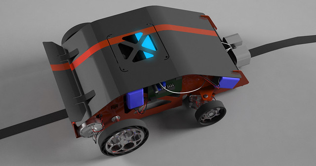
Each robot is required to have an infrared emitter mounted at a height of six inches. Therefore, we designed a shell for the mounting of the said emitter, as well as for cosmetic purposes.
A spoiler was made, just for fun. It is spot-welded on. Both the shell and the spoiler are made in 24-gauge steel, and powder-coated black. A red racing stripe was added using red tape.
The latest version of the shell fits both chassis v4 and chassis v3.5. Another shell, made of aluminum, was originally designed for chassis v2 and v1. That was scrapped after chassis v2 turned out to not work.
Wheels and Tyres
The wheels on Gadget are made of polycarbonate, and the tyres are made of rubber. The rear wheels are designed to be reminiscent of Lamborghini wheels with five 'portholes'. The rear tyres are especially innovative, and there is a good reason why they must be designed in that way. Our robot has no suspension system, but all four wheels must be on the ground - especially the rear wheels, since there is a differential (car would not move if one wheel slips). Therefore, the tyres must have some ability to deform in order to ensure that all wheels are on the ground. Daniel has carefully designed these tyres so that this degree of flexion is achieved.
![]()
Electrical Design
The electrical aspect of Gadget was shared between Billy and Adrien. Billy was largely responsible for designing and soldering the comparator circuit for the QRD1114 sensors for tape tracking; Adrien was largely responsible for the circuits involving the rangefinder and motor control. Adrien also designed and constructed the infrared detector and filter, although this was not used.
QRD1114 Comparator Circuit
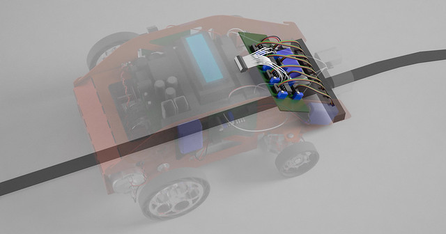
Billy soldered this circuit, which converts the analog signals of the QRD1114 sensors to digital signals. It uses one dual comparator for every two QRD sensors. Although it was originally planned to have eight potentiometers, one to calibrate each QRD sensor, only four were used in the end, because after soldering three potentiometers it became apparent that QRD1114 sensors were sufficiently alike that only one potentiometer would suffice to calibrate them all. Besides, tuning the potentiometer is a lot more tedious than simply giving the sensor a physical nudge with a popsicle stick, which usually accomplishes the same effect.
Rangefinder Circuit
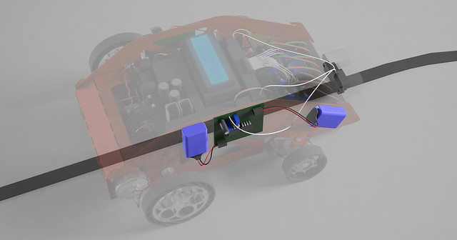
Adrien soldered the rangefinder comparator circuit, which converts the analog signal of the rangefinder to a single-bit digital signal, controlled by a potentiometer.
To mitigate the issues of noise from extraneous infrared, a low-pass resistor-capacitor filter was constructed. In addition, the rangefinder is encased in a solid metal block that is grounded to reduce noise.
Infrared Sensor
Adrien soldered a sallen-key band pass filter, amplifier, dc-block, and peak detector for the infrared sensor circuit. Since an infrared emitter is mounted on each robot, such an infrared sensor would allow Gadget to avoid other robots. However, this idea was scrapped in favour of the rangefinder - a decision that ultimately proved to be a bad one.